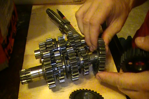
The transmission is a collection of gears that change the revolution ratio of the drive shaft which rotates the rear tire. The input to this system comes from the clutch which is rotated by the crank shaft via a gear driven system or a primary chain. This section I will provide an example of how gears work and this example will be the 1982 Maico 490 GS transmission.
The Maico 490 GS has three shafts in the transmission. The "MainShaft" which is the power input, the main shaft is attached to the clutch and rotates the transmission gears. The "Layshaft" which is the shaft that is rotated by the main shaft and finally the drive shaft which is rotated by the lay shaft. The full sequence of events that occur in the Maico 490 GS are as follows.
- The crankshaft rotates the crank shaft gear.
- The crankshaft gear is connected to the primary chain and this rotates the clutch.
- The clutch is connected to the main shaft and rotates the gears on this shaft.
- The shifting cam has positioned the shifting forks so that a certain gear ratio is set in the transmission.
- The mainshaft gears rotate the layshaft gears.
- The layshaft gears rotate the drive shaft gear.
- The drive shaft contains the front sprocket and this rotates.
- The front sprocket is connected to the rear sprocket via a chain and this rotates the rear tire.
That is the full sequence of events that occur without the details of the combustion engine, electrical system or explaining how the clutch works. The following is an image that shows the full layout of the 1982 Maico 490 GS transmission.
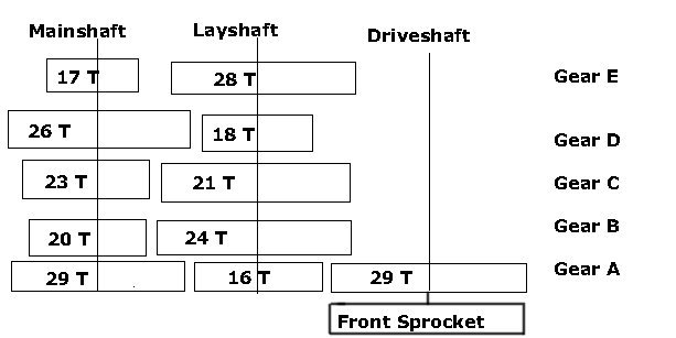
The following is a description of each of the gears on each of the shafts. Please note that "Gear A", "Gear B", etc. do not pertain to the gear that they represent when shifting but just the gear they represent physically by view. The gears that represent the actual gears used when shifting will be detailed below. The A, B, etc. are just for illustration purposes.
- Mainshaft Gear A - This gear spins freely on the shaft. This gear can only be turned by Gear B.
- Mainshaft Gear B - The shifting fork positions this gear and it contains dogs on both sides and so it turns Gear A or Gear C. This gear always turns with the mainshaft.
- Mainshaft Gear C - This gear spins freely on the shaft. This gear can only be turned by Gear B.
- Mainshaft Gear D - This gear spins freely on the shaft. This gear can only be turned by Gear E.
- Mainshaft Gear E - The shifting fork positions this gear and it contains dogs that fit into Mainshaft Gear D. This gear always turns with the mainshaft.
- Layshaft Gear A - This gear always rotates with the layshaft. This gear is used to rotate the driveshaft.
- Layshaft Gear B - This gear spins freely on the layshaft. This gear contains dogs that allow it to rotate with Gear C/D.
- Layshaft Gear C & D - Gear C and Gear D is actually a single physical piece of metal that always rotates with the lay shaft and is positioned by a shifting fork. The gear also contains dogs on both sides that allow it to rotate with Gear B or Gear E.
- Layshaft Gear E - This gear spins freely on the layshaft. This gear contains dogs that allow it to rotate with Gear C/D.
- Driveshaft Gear A - This gear always spins with the driveshaft. The front sprocket is on the end of the drive shaft.
The next piece of the puzzle is the shifting cam. The shifting cam is usually circular however in the Maico it is a plate. This plate is moved when you shift gears and the shifting forks are repositioned. The positioning of the shifting forks is what locks a particular gear pattern in place. Let's take a look at the Maico shifting cam plate for the GS pictured below.
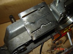
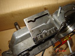
The indents on the gear represent the gears 1-5 and neutral. Neutral is the small hole indented between 1st and 2nd gear. The shifting forks sit in the grooves of the shifting cam and each time you move into gear they reposition the transmission. Let's see how this works with the 490 GS.
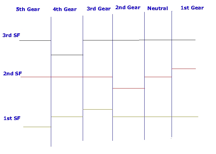
The top line is the shifting fork that moves the Gear E on the mainshaft. The middle line is the shifting fork that moves Gear C/D on the layshaft. The bottom line is the shifting fork that moves Gear B on the mainshaft.
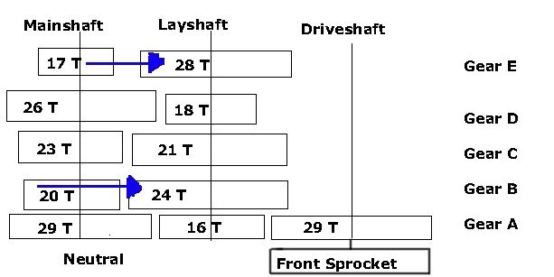
We will start with neutral since this is where your put your bike when you start it (unless you're drift starting). We should start with the obvious gears which are the gears on the mainshaft that actually turn with the main shaft which are gears B and E. The shifting forks in the neutral position none of the dogs are locked into any of the gears. Gear E on the mainshaft will turn Gear E on the layshaft however Gear E on the layshaft does not spin the layshaft so it rotates freely. Gear B on the mainshaft will rotate Gear B on the layshaft however Gear B on the layshaft does not spin the layshaft and will rotate freely.
Since none of the dogs are locked in place these gears will just spin as per the picture below.
You're ready to go so you shift the bike into 1st gear, what happens? If you refer back up to the shifting fork diagram above you can see that the middle shifting fork moves up. The middle shifting fork is connected to the layshaft Gear C/D so Gear C/D locks into the layshaft gear E. The mainshaft Gear E is now turning the layshaft Gear E which is then turning the layshaft Gear A since layshaft Gear C/D is locked into place with gear E. The layshaft Gear A is now turning the driveshaft Gear A that in turn is rotating the front sprocket. The transfer of power is seen in the diagram below (Yes the orientation is as if you are looking from underneath the motor at the transmission).
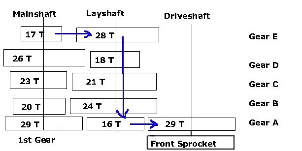
The gear ratio is then 28/17 = 1:1.64. The layshaft and drive shaft are always on a ratio of 29/16 = 1:1.81. This means that for every 1 revolution of the layshaft the mainshaft has to turn 1.64 revolutions and for the driveshaft to turn 1 revolution the layshaft has to turn 1.81 revolutions. This means that for the driveshaft to turn 1 revolution the mainshaft has to turn 1.81*1.65 = 2.96 so the transmission is at a 1:2.96 ratio in relation to input from the clutch. (See Sprockets and Gearing for more explaination about gear ratios).
Let's shift the bike into 2nd gear now and let's check out the shifting fork pattern diagram above. 2nd gear shifts the middle shifting fork which moves layshaft Gear C/D down. The shifting fork pattern shows that this should now lock into layshaft Gear B because it goes down past its neutral position. This allows mainshaft Gear B to rotate layshaft Gear B and rotate the layshaft itself as shown in the diagram below.
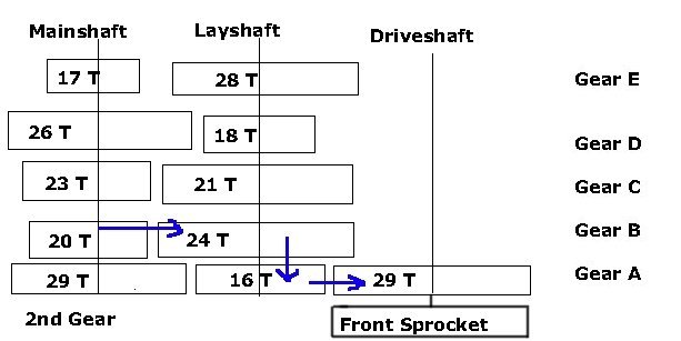
This now provides a gear ratio of 24/20 = 1:1.2 for the gear and 1.2*1.81 = 1:2.17 ratio for the transmission output.
Shifting into 3rd gear we can see that the middle shifting fork has moved back into its neutral position. The shifting fork that now moves out of its neutral position is the first shifting fork and this moves the mainshaft Gear B to lock with mainshaft Gear C. This allows mainshaft Gear C to turn layshaft Gear C as seen in the diagram below.
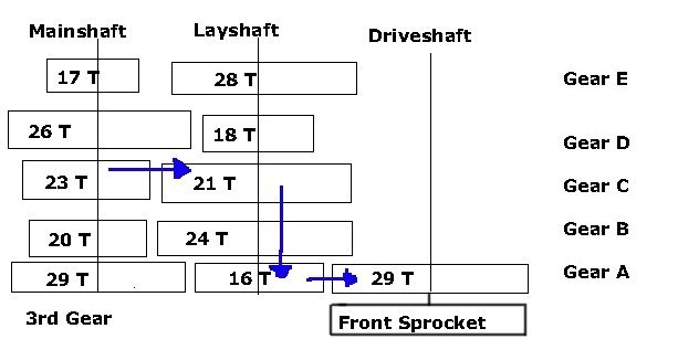
This now provides a gear ratio of 21/23 = 1:0.91 for the gear and 0.91*1.81 = 1:1.65 ratio for the transmission output.
Shifting into 4th gear we can see that the 1st and 2nd shifting forks are back into thier neutral positions however shifting fork 3 has now moved down. This shifting fork locks the mainshaft Gear E into the mainshaft Gear D and thus the mainshaft Gear D turns the layshaft Gear D as seen in the picture below.
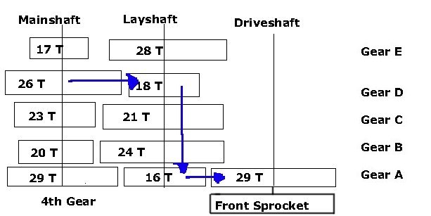
This now provides a gear ratio of 18/26 = 1:0.69 for the gear and 0.69*1.81 = 1:1.24 ratio for the transmission output.
Shifting into the final 5th gear we can see that the 2nd and 3rd shifting forks are back into thier neutral positions however shifting fork 1 has now moved down. This shifting fork locks the mainshaft Gear B into the mainshaft Gear A and thus the mainshaft Gear A turns the layshaft Gear Aas seen in the picture below.
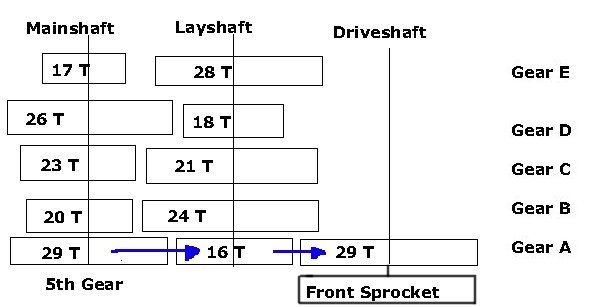
This now provides a gear ratio of 16/29 = 1:0.55 for the gear and 0.55*1.81 = 1:1 ratio for the transmission output. This would be expected the gears on both sides of the 16 tooth gear are the same at 29 teeth.
The next problem is to relate this to RPMs which is how fast the crankshaft would be spinning. The crankshaft has a gear which has 21 teeth and the clutch which has 39 teeth so 39/21 = 1:1.86. Relating this to RPMs this means that at 8,000 RPMs the mainshaft would be spinning at 8000/1.86 = ~4300 rotations.
Let's figure out how fast the bike will be traveling then based on the Tire Math that was discussed before. Given that the transmission is now 1:1 in the GS model in 5th gear if you had a front sprocket of 13 teeth, a rear sprocket of 52 teeth and a tire of true diameter of ~26" (18" rim with a tire on it), the speed at which the bike would be traveling is 52/13 = 1:4 ratio (1 rotation of the rear tire is 4 rotations of the drive shaft). The drive shaft would rotate at 4300 RPM when the motor is operating at 8000 RPM which means the tire spins at 4300/4 = 1075 rotations a minute. 26*3.14 = 81.64" or 6.8 feet for every rotation. 6.8 feet * 1075 = 7310 feet * 60 minutes = 438,600 feet an hour or 438,600 feet / 5,280 feet (1 mile) = 83 miles an hour.
Please note that this is just an estimate and not actual fact. However, for fun let's calculate the speed at 8,000 RPM for each gear.
- 1st - 1:2.96 = ~4300/2.96 = 1452.7/4 = 363.17*6.8 = 2469.556*60 = 148173.36/5280 = 28 MPH
- 2nd - 1:2.17 = ~4300/2.17 = 1981.5/4 = 495.37*6.8 = 3368.516*60 = 202110.96/5280 = 38 MPH
- 3rd - 1:1.65 = ~4300/1.65 = 2606/4 = 651.5*6.8 = 4430.2*60 = 265812/5280 = 50 MPH
- 4th - 1:1.24 = ~4300/1.24 = 3467.7/4 = 866.92*6.8 = 5895.056*60 = 353703.36/5280 = 67 MPH
Here is a chart with the estimated MPH for each RPM at each gear based on the above formulas.
| 1000 | 3000 | 5000 | 6000 | 7000 | 8000 | 9000 | |
| 1st Gear | 3.51 | 10.53 | 17.54 | 21.05 | 24.56 | 28.07 | 31.58 |
| 2nd Gear | 4.79 | 14.36 | 23.93 | 28.72 | 33.50 | 38.29 | 43.08 |
| 3rd Gear | 6.29 | 18.88 | 31.47 | 37.77 | 44.06 | 50.36 | 56.65 |
| 4th Gear | 8.38 | 25.13 | 41.88 | 50.26 | 58.63 | 67.01 | 75.38 |
| 5th Gear | 10.39 | 31.16 | 51.93 | 63.32 | 72.70 | 83.09 | 93.48 |
Try out the Speed Calculator.

